
How to Calculate the Safe Slope Ratio for Wheelchair Ramps
Engineering Ground Truth: Ramp Slope Formulas & Kinematic Thresholds
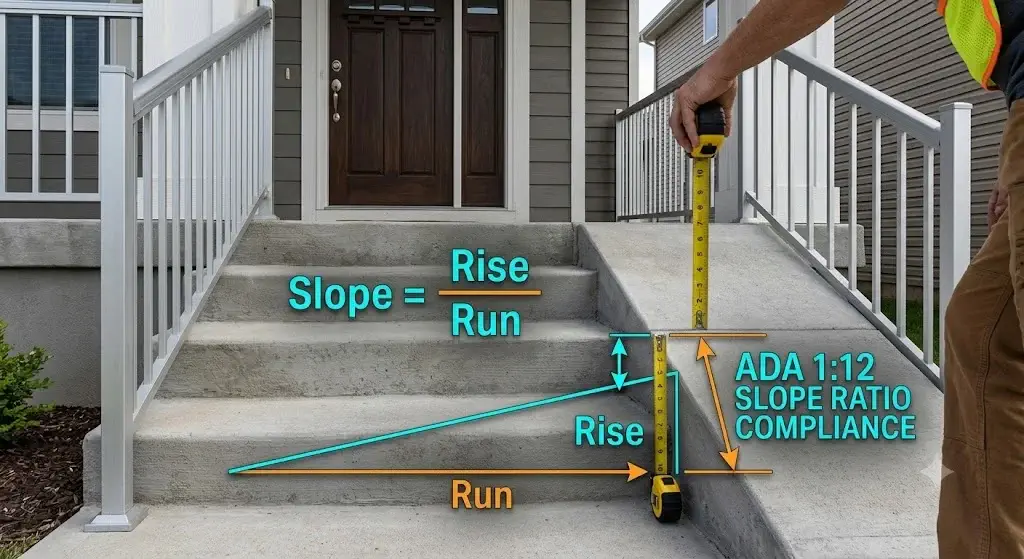
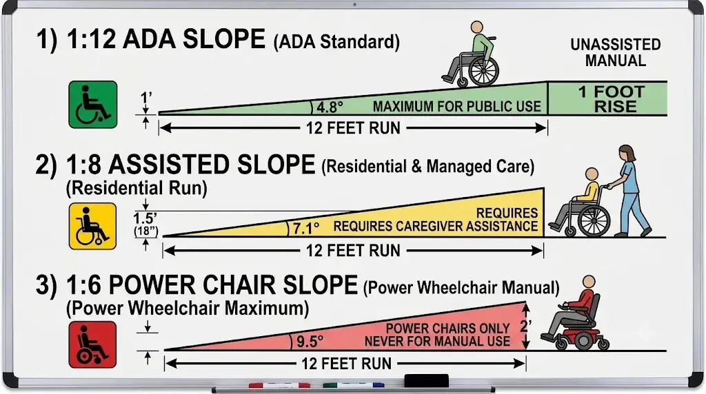
Learning how to calculate the safe slope ratio for wheelchair ramps requires applying the mathematical relationship Slope = Rise ÷ Run against occupant biomechanical limits. Under ADA Standards Section 405, the mandatory maximum slope for public accessibility is 1:12 (one inch of vertical rise for every 12 inches of horizontal run, representing a 4.76° angle or 8.33% grade). For residential retrofits where yard setback is restricted, a 1:8 slope ratio (7.13° angle) accommodates manual wheelchairs pushed by an able-bodied caregiver, while an occupied power wheelchair or mobility scooter can operate up to a 1:6 slope ratio (9.46° angle) without motor stalling or front caster lifting. Exceeding 1:6 shifts the occupant’s center of mass beyond the rear axle, triggering catastrophic backward rollover accidents.
- The Fundamental Formula: Total Run (feet) = Total Vertical Rise (inches) at 1:12 ratio; Total Run (feet) = Total Vertical Rise (inches) ÷ 1.5 at 1:8 ratio.
- Maximum Single Run Limits: ADA guidelines mandate a 60-inch flat resting landing after every 30 inches of vertical rise or 30 feet of continuous ramp run.
- Caster Ingress Deflection: Any vertical threshold exceeding 0.5 inches requires beveled transition plates to prevent front wheel entrapment.
Quick Reference Specification: Wheelchair Ramp Slope Ratios and Step Run Requirements
The technical specification matrix below compares the 3 standardized slope ratios across common residential step heights, contrasting incline angles, push forces, and clinical safety applications:
| Slope Ratio | Incline Angle | Grade (%) | Run for 1 Step (7″ Rise) | Run for 2 Steps (14″ Rise) | Clinical & Safe Application |
|---|---|---|---|---|---|
| 1:12 (ADA Standard) | 4.76° Pitch | 8.33% | 7.0 Feet (84″) | 14.0 Feet (168″) | Independent manual wheelchairs; zero caregiver assistance needed. |
| 1:8 (Residential Assisted) | 7.13° Pitch | 12.50% | 4.7 Feet (56″) | 9.3 Feet (112″) | Assisted manual transit; requires strong caregiver forward thrust. |
| 1:6 (Power Chair Max) | 9.46° Pitch | 16.67% | 3.5 Feet (42″) | 7.0 Feet (84″) | High-torque electric wheelchairs and mobility scooters only. |
| 1:4 (Unsafe / Hazard) | 14.04° Pitch | 25.00% | 2.3 Feet (28″) | 4.7 Feet (56″) | Strictly Prohibited: Immediate backward tip-over rollover risk. |
Biomechanical Vectors: Gravitational Drag Multiplies Upper Extremity Strain
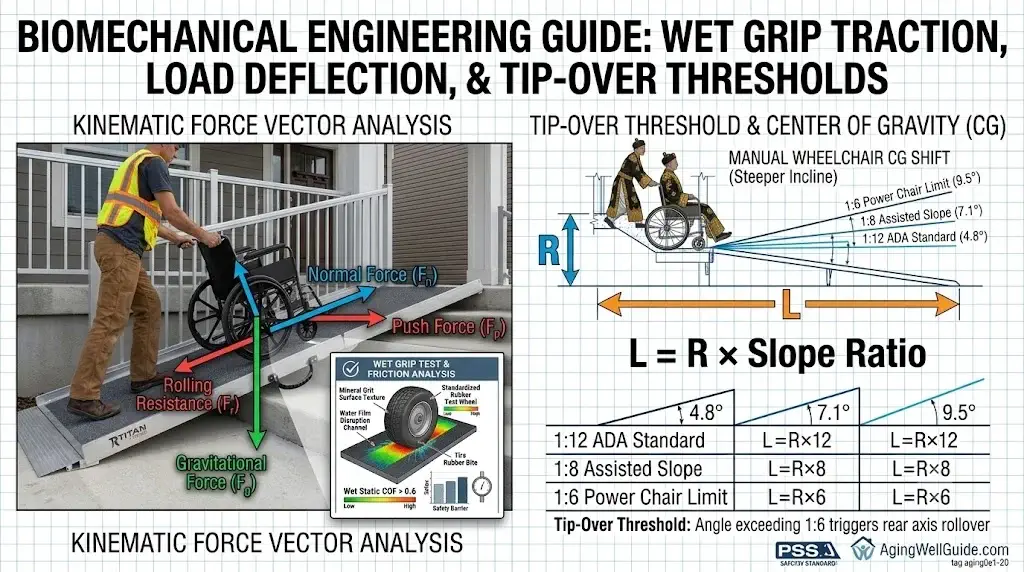
Steep ramp angles exponentially increase the force required to propel a manual wheelchair forward. When navigating a horizontal surface, rolling resistance is primarily determined by wheel tire friction and caster bearing quality. However, as the incline angle increases, gravity splits into two force vectors: a normal force pressing the tires against the aluminum deck and a downward parallel force pulling the chassis backward.
The physiological and mechanical impact of varying slope angles includes:
- Upper Extremity Strain: At a 1:12 slope (4.76°), an occupant in a combined 200-lb chair setup must exert approximately 16.6 lbs of steady forward thrust. At a 1:8 slope, that requirement jumps to 25.0 lbs of force, exceeding the muscular endurance of 80% of elderly manual wheelchair self-propellers.
- Backward Tip-Over Mechanics: Pushing uphill rotates the occupant’s torso rearward, shifting their center of mass behind the rear axle pivot line. If the front casters lift off the deck, standard rear anti-tip wheels strike the ramp surface, causing the drive wheels to lose frictional contact.
- Doorway Threshold Transition Clashes: When ramp runs terminate abruptly at door sills, small 4-inch caster wheels jam. Combine exterior ramp runways with low-profile doorway threshold ramps to ensure zero-lip interior transitions.
Calculation Methodology: How to Calculate the Safe Slope Ratio for Wheelchair Ramps Step by Step
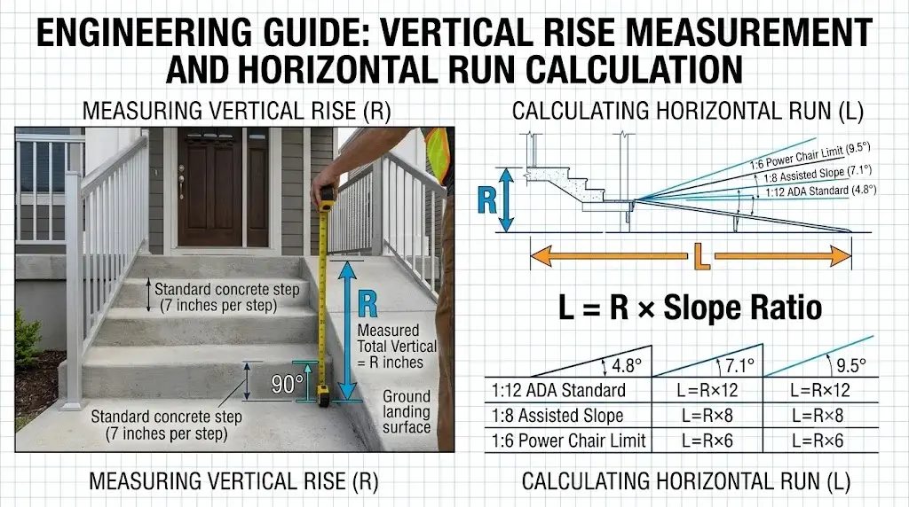
Accurate ramp dimensioning requires converting the total vertical rise into linear ramp run using basic trigonometric ratios. Standard residential steps in the United States average 7.0 to 7.5 inches of rise per tread. Failing to measure from the finished ground plane to the exact top sill elevation leads to selecting ramps that are too short and dangerously steep.
The 4-Step Engineering Calculation Protocol
- Determine Total Vertical Rise (R): Drop a plumb bob or rigid level from the highest threshold point to the ground. Measure the total vertical drop in inches (R). Example: 3 steps × 7 inches = 21 inches total rise.
- Select the Operational Slope Factor (S):
• For independent manual use: S = 12 (ADA Section 405 compliant).
• For caregiver-assisted manual use: S = 8 (Residential standard).
• For occupied electric power chairs: S = 6 (Maximum mechanical limit).
- Calculate Required Horizontal Run (L in inches):
Run Length (L) = Vertical Rise (R) × Slope Factor (S)
Example at 1:12 ratio: 21 inches × 12 = 252 inches (21.0 feet).
Example at 1:8 ratio: 21 inches × 8 = 168 inches (14.0 feet). - Account for Folding Hardware Clearances: Verify that the surrounding landing space can accommodate the total unfolded length. For porch steps spanning 6 to 12 inches, compare multi-section setups in our roundup of portable folding wheelchair ramps.
Architectural Compliance: ADA Section 405 Dictates Landings and Edge Protection
ADA Section 405 establishes strict structural mandates to prevent wheel derailments and structural collapse on extended runs. A ramp is not simply an inclined board; it is an architectural pathway governed by strict landing dimensions, side curb heights, and cross-slope limits that guarantee lateral stability during transit.
Key architectural mandates under federal accessibility standards include:
- Clear Width Requirements (§405.5): The minimum clear width between handrails or side curbs must be at least 36.0 inches (915 mm) to accommodate bariatric wheelchairs and user hand clearances on push-rims.
- Maximum Continuous Rise (§405.6): The rise for any single ramp run shall be 30.0 inches (760 mm) maximum. Ramps exceeding 30 inches of vertical climb require intermediate resting landings measuring a minimum of 60.0 inches in length.
- Top and Bottom Landings (§405.7): Landings must be level (maximum cross-slope of 1:48) and measure at least 60 inches by 60 inches where ramps change direction to permit a standard 360-degree wheelchair turning radius.
- Edge Protection Curbs (§405.9): Ramps with drop-offs must incorporate continuous side curbs measuring at least 2.0 inches (51 mm) high to physically block front casters from driving over the edge. Commercial multifold units like those examined in our Titan Fitness multifold ramp review incorporate extruded aluminum curbs for this exact compliance.
Drivetrain Dynamics: Electric Motors Tolerate Steeper Inclines Than Human Muscles
Electric mobility equipment utilizes electromechanical torque to overcome inclines that would exhaust manual pushers. While an elderly individual or post-stroke patient cannot generate the continuous arm wattage needed to climb a 1:8 slope, twin brushless 24-volt DC motors in power chairs easily conquer steeper inclines up to 1:6.
However, steep inclines introduce severe mechanical risks for motorized equipment:
- Dynamic Braking Skid: When descending a 1:6 slope in wet weather, the electromagnetic brakes on heavy 300-lb power chairs can lock the drive tires, causing the chair to skid uncontrollably down smooth aluminum ramps.
- Thermal Cutoff Hazards: Sustained climbs exceeding 9.5 degrees trigger power chair motor controller circuit breakers, leaving occupants immobilized halfway up the incline.
- Surface Traction Requirements: Never operate power chairs on steep residential ramps unless the runway features punched-aluminum traction tread or baked-on mineral grit coatings that maintain a wet friction coefficient above 0.6.
Building an Integrated Whole-Home Mobility Ecosystem
Knowing how to calculate the safe slope ratio for wheelchair ramps prevents outdoor falls and equipment stalls. To extend fall protection and barrier-free biomechanics inside your home, integrate your ramp design with these essential medical solutions:
- Smooth out raised door thresholds by installing durable doorway threshold ramps.
- Select multi-step exterior bridges from our tested guide to portable folding wheelchair ramps.
- Support sit-to-stand knee biomechanics in the living area by reviewing the best power lift recliners for seniors.
- Secure nighttime bedside transfers against postural hypotension with sturdy bed assist rails with legs.
Frequently Asked Questions (FAQ)
What is the maximum slope ratio allowed for residential wheelchair ramps?
While ADA Section 405 legally mandates a 1:12 slope ratio (4.76 degrees) for commercial facilities, private residential installations permit a 1:8 slope ratio (7.13 degrees) for manual chairs pushed by an able-bodied caregiver or a 1:6 ratio (9.46 degrees) for occupied power chairs when yard space is restricted.
How do you calculate the ramp length needed for a 2-step porch?
Two standard residential steps equal 14 inches of vertical rise (7 inches per step). At an ADA 1:12 ratio, you need 14 feet (168 inches) of ramp run. Under an assisted residential 1:8 ratio, you need 9.3 feet of ramp run, while a 1:6 ratio requires a 7-foot portable ramp.
What happens if a wheelchair ramp slope is too steep?
A slope steeper than 1:6 causes manual users to tip backward past their rear axle center of gravity. For power chairs, excessive slope triggers motor thermal overload, drive-wheel slippage on wet decks, and dynamic brake lockup during descent.
When are rest landings legally required on a wheelchair ramp run?
ADA Section 405.6 mandates that ramps cannot exceed a continuous vertical rise of 30 inches without an intermediate level resting landing measuring at least 60 inches in length and the full width of the ramp runway.
