
How to Replace an Okin Lift Chair Motor and Actuator
Executive Engineering Summary: Okin Actuator Replacement
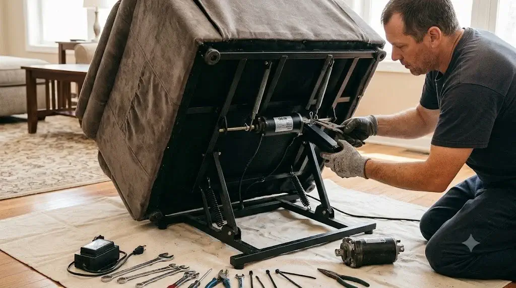
Learning how to replace an okin lift chair motor and actuator requires diagnosing whether failure stems from the electrical power supply, hand control switch, or the linear worm-drive motor assembly itself. Replacing an actuator involves disconnecting 29V DC transformer power, flipping the recliner frame onto protective padding, removing the front and rear steel clevis mounting pins, and bolting in an OEM-matched actuator matching exact stroke length and retracted pin-to-pin dimensions.
- Dimensional Verification: Replacement units must match the existing actuator stroke length (e.g., 333mm / 13.11 in) and retracted mounting dimension within ±2mm to avoid frame binding.
- Thrust Rating Standards: Heavy-duty senior chairs demand minimum push ratings of 4,000N to 6,000N (Newtons) to safely lift occupants weighing up to 375–500 lbs.
- Electrical Cable Interface: Modern Okin drives utilize a 2-pin flat/round plug for DC power input and an auxiliary 5-pin round DIN socket for remote hand pendants.
- Silo System Integration: Actuator maintenance directly impacts overall Mcombo lift chair durability and relies heavily on properly configured battery backup wiring to prevent seniors from being stranded during municipal power cuts.
Quick Reference Specification: How to Replace an Okin Lift Chair Motor and Actuator
Executing a successful how to replace an okin lift chair motor and actuator project requires matching core electromechanical specs against OEM manufacturing tolerances. The matrix below outlines specifications for common Okin actuator families:
| Engineering Metric | Okin Deltadrive (Standard) | Okin Betadrive / JLDQ Series | Mechanical & Safety Relevance |
|---|---|---|---|
| Operating Voltage | 24V – 29V DC continuous | 24V – 29V DC continuous | Operates safely under standard low-voltage DC transformers |
| Push Force (Thrust) | 4,000 N (approx. 900 lbs) | 6,000 N (approx. 1,350 lbs) | High thrust prevents internal gear stripping under bariatric loads |
| Typical Stroke Length | 333 mm (13.11 inches) | 200 mm to 333 mm adjustable | Must match exactly to ensure complete recline and standing lift |
| Retracted Install Distance | 15.35 to 15.7 inches (390-399mm) | 15.6 to 18.5 inches (395-470mm) | Distance between clevis hole centers; misfits cause frame binding |
| Internal Gearing Material | Reinforced Nylon / POM Polymer | Hardened Composite Worm Gear | Absorbs impact shock and minimizes operating decibel levels |
| Connector Plugs | 2-pin flat/round + 5-pin DIN | 2-pin flat/round + 5-pin DIN | Plug-and-play wiring matching universal hand control pendants |
| Installation Time | 30 to 45 minutes | 30 to 45 minutes | Requires basic household hand tools and no wire splicing |
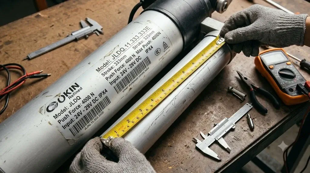
Technical identification: verifying the stroke length, minimum install dimension, and model number on the OEM Okin linear actuator label.
Systematic Multimeter Diagnostics Isolate Actuator Failure from Power Supply Issues
A completely unresponsive lift chair does not automatically mean the linear actuator motor has burned out. Before spending money on an expensive replacement motor, the technician or family caregiver must methodically verify power continuity across the three primary electrical modules: the AC wall outlet, the external 29V DC switching power supply transformer, and the 5-pin hand control switch.
Follow these bench diagnostics to isolate the mechanical fault:
- Check Transformer LED Status: Inspect the LED light on the external transformer brick sitting on the floor. A solid green light indicates operational 24V–29V DC output. A completely dark or flickering light indicates a damaged power cord or blown transformer capacitor.
- Probe Output Voltage with Multimeter: Insert digital multimeter test probes into the 2-pin female output connector (one flat pin, one round pin). The readout should measure consistently between 28.5V and 29.5V DC. If voltage drops to zero when pressing the hand control, replace the power supply unit.
- Listen for Motor Relay Clicks: If the power supply outputs 29V DC and you hear an audible mechanical “click” inside the motor housing when pressing the hand pendant—yet the lift mechanism fails to extend—the internal nylon worm drive gear is stripped or the drive screw has seized.
- Inspect Cable Sheathing: Check the entire length of the hand pendant cord. Because lift chair scissor linkages move constantly, cables frequently get pinched in the steel frame, severing internal copper conductors.
When an actuator motor hums loudly or slips under the occupant’s weight, the internal composite worm gear has lost its teeth. At this stage, repairing internal gears is cost-prohibitive compared to replacing the sealed linear drive assembly.
Accurate Actuator Label Decoding Guarantees Precise Frame Stroke Compatibility
Ordering the correct replacement actuator requires reading the manufacturer’s data label affixed to the aluminum drive tube or plastic motor housing. Okin, Limoss, Kaidi, and Dewert motors share similar aesthetic designs, but internal stroke lengths and clevis mount geometries differ across chair models. Installing an actuator with an incorrect stroke length will bend the steel scissor linkages or prevent the footrest from closing flush.
Locate the following critical parameters on your Okin label (e.g., Okin Deltadrive model 1.28.000.131.30 or JLDQ.11.156.333):
- Stroke Length (Hub): This metric specifies the maximum travel distance of the silver telescoping aluminum piston tube. The standard stroke across full-range power lift recliners is 333mm (13.11 inches). Compact or dual-motor chairs may utilize shorter 200mm or 250mm strokes.
- Minimum Installation Dimension (Einbaumaß): This is the exact distance between the center of the rear motor mounting hole and the center of the front piston mounting hole when the actuator is fully retracted. Standard measurements range from 390mm to 399mm (15.35 to 15.7 inches).
- Max Push Force: Indicated in Newtons (e.g.,
Push: 4000Nor6000N). Never install a replacement motor rated below your chair’s original factory thrust rating.
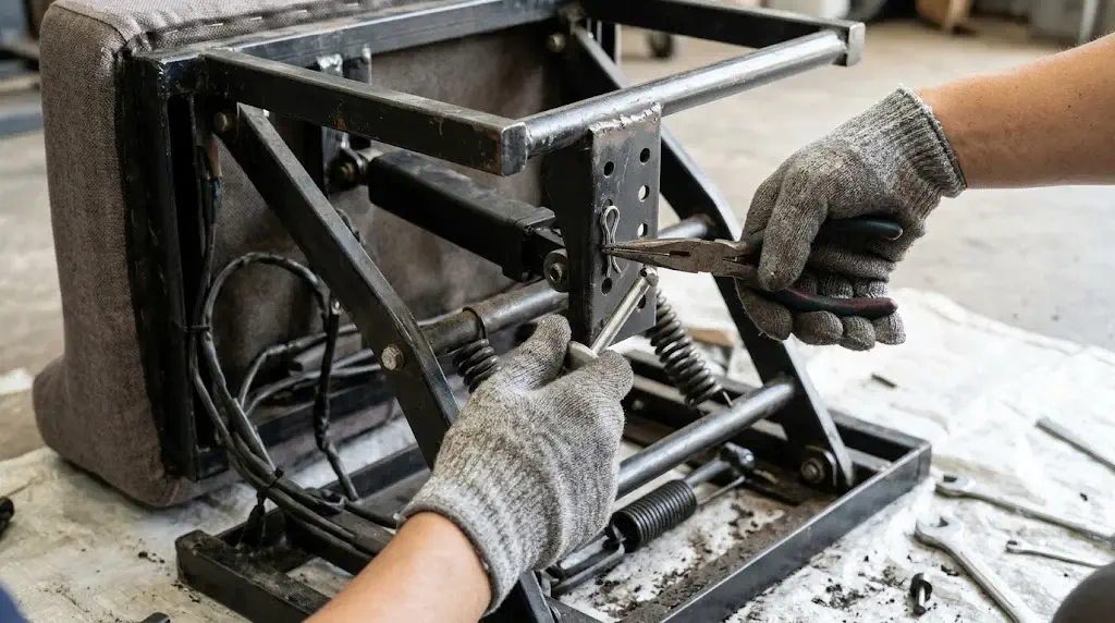
Mechanical disassembly: extracting the steel hairpin cotter clip and sliding the clevis retaining pin out from the rear motor mount bracket.
Safe Chair Frame Inversion Precedes Clevis Pin and Actuator Removal
Replacing an actuator safely requires positioning the chair to access the undercarriage without putting strain on the scissor linkages. Because high-density power lift recliners weigh between 110 and 145 lbs, always recruit an assistant or use proper lifting mechanics to tip the chair onto its side or front face without tearing the upholstery.
Follow this bench-tested sequence to remove and install the linear actuator:
Phase 1: Disconnection & Frame Inversion
1. Unplug Main AC Power: Disconnect the chair’s power transformer from the 110V wall outlet. Remove any 9V emergency backup batteries installed inside the power supply brick to eliminate residual electrical charge.
2. Invert the Recliner: Lay a heavy moving blanket on the floor to prevent hardwood scratches or carpet snagging. Carefully roll the lift chair forward onto its armrests and headrest, exposing the tubular steel scissor chassis and actuator mechanism.
Phase 2: Cable Disconnection & Pin Extraction
3. Disconnect Electrical Leads: Locate the 2-pin flat/round DC power lead and the 5-pin round hand pendant cable plugged directly into the motor housing. Unclip the plastic locking latches and separate the connectors. Snip any factory zip ties securing the wires to the frame.
4. Remove the Front Stroke Tube Clevis Pin: Using needle-nose pliers, straighten and extract the split cotter pin or pull the reusable hairpin clip from the front clevis pin. Gently tap the smooth steel pin out of the bracket connecting the aluminum extension tube to the footrest mechanism.
5. Remove the Rear Motor Clevis Pin: Support the heavy rear plastic motor housing with one hand to prevent it from dropping. Pull the rear retaining clip, extract the rear clevis pin, and lift the entire defective actuator assembly out of the chassis.
Phase 3: Mounting and Calibrating the New Actuator
6. Dry-Fit & Align Mounting Brackets: Position the new OEM Okin actuator into the chassis. Insert the rear clevis pin first, securing it with its cotter hairpin clip. Check whether the front mounting hole aligns with the frame bracket. If the front hole is off by a few millimeters, manually rotate the silver stroke tube clockwise or counter-clockwise on its internal threads to shorten or lengthen the retracted profile until the holes align perfectly.
7. Insert Front Clevis Pin & Re-clip: Slide the front clevis pin through both the frame bracket and the actuator stroke eyelet. Lock the retaining clip firmly into place.
8. Reconnect Wiring Harnesses: Firmly re-insert the 2-pin DC power plug and 5-pin hand control DIN connector, ensuring locking tabs click. Bundle and anchor loose cords along the stationary base rails with zip ties—leaving adequate slack so wires never get pinched during scissor movement.
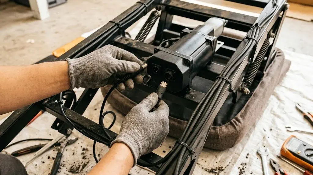
Electrical integration: securing the 2-pin DC power cable and 5-pin DIN hand remote connector with protective strain relief.
Universal Okin Linear Drives Provide Direct Drop-In Replacement for Popular Recliners
Sourcing an exact OEM actuator replacement avoids the frustration of mismatched clevis pin holes or incompatible wiring sockets. These three proven replacement linear actuators and universal power accessories match standard Okin drive footprints across modern lift recliners:
1. Okin JLDQ.11.156.333 Universal Linear Actuator Motor
This authentic Okin JLDQ linear actuator is the gold-standard workhorse powering the vast majority of residential lift chairs. Featuring a standard 333mm (13.11-inch) stroke and a 15.6-inch retracted installation profile, it drops directly into existing scissor mounts without modification. Its heavy-duty 750W composite worm-drive motor produces whisper-quiet linear motion with an upgraded 4,000N push capacity.
2. Lojiraz 29V 2A AC/DC Switching Power Supply Adapter Kit
When diagnosing a lift chair that refuses to move, replacing a dead or surging transformer is the quickest fix before unbolting the motor. This Lojiraz 29V 2A switching adapter delivers stable DC power through an 8.2-foot heavy-duty copper cord with built-in surge protection, over-temperature defense, and short-circuit protection. It features the industry-standard 2-pin connector (one flat pin, one round pin) with a locking clip that fits Okin, Limoss, Pride, and Ashley power recliners.
3. AlveyTech Standard 2-Button 5-Pin Hand Control with USB Port (CTL151305)
A failing remote control pendant with severed copper wiring frequently mimics a dead actuator motor. The AlveyTech replacement remote features a standard 5-pin circular DIN connector compatible with Okin, Dewert, and Mega Motion lift chair motors. It offers crisp, tactile up/down micro-switches designed for arthritic senior hands, a flexible coiled cord that resists scissor-mechanism pinches, and an integrated side USB charging port for phones or tablets.
Unloaded Cycle Testing Confirms Smooth Scissor Linkage Articulation
Never allow an occupant to sit in a repaired lift chair immediately after bolting in a new motor. Before placing the chair upright on its feet, perform two complete “unloaded” cycles—running the actuator through its full extension and retraction—while observing the steel scissor linkages from below. Listen closely for clicking sounds, binding resistance, or cable pinching against the frame crossmembers.
Once the chair passes unloaded testing, return it upright and test it with an adult occupant. Verify that the footrest closes completely without contacting the floor and that the standing lift position elevates smoothly to a 45-degree angle without motor hesitation.
To extend the working life of your new Okin actuator, apply white lithium grease to the steel frame pivot rivets every 12 months. Never lubricate the internal plastic worm gear or aluminum stroke tube with petroleum-based penetrating oils (like WD-40), as solvents degrade internal nylon gear teeth and attract carpet dust.
Frequently Asked Questions About Okin Lift Chair Motor Replacement
How do I know if my Okin lift chair actuator motor is bad or just the power supply?
A proper how to replace an okin lift chair motor and actuator process starts with testing the power supply. Inspect the external power brick on the floor: a solid green LED indicates working DC output. If the light blinks or stays unlit when pressing the hand control, the transformer or remote cord is defective. If the transformer outputs 29V DC on a multimeter but the motor only clicks or hums without moving, the internal nylon gear is stripped and the actuator assembly must be replaced.
What specifications must match when ordering a replacement Okin actuator?
You must verify three key specifications from the motor label: the stroke travel length (commonly 333mm / 13.11 inches), the retracted minimum install dimension between hole centers (typically 15.35 to 15.7 inches), and the electrical cable interface (standard 2-pin flat/round power jack and 5-pin DIN remote socket).
Can I replace an Okin Deltadrive with an Okin Betadrive or JLDQ model?
Yes, provided the stroke length, minimum install dimension, and clevis pin hole diameters match. Universal OEM models like the Okin JLDQ.11.156.333 series are engineered to drop directly into scissor-frame mounts that previously utilized older Deltadrive or Betadrive variants.
Do I need special tools to remove and install a lift chair actuator?
No special machinery is required. All you need are needle-nose pliers to remove the steel cotter hairpin clips, a small screwdriver or socket wrench for ground wires, wire cutters/zip ties for cable management, and a digital multimeter to verify 29V DC power.
