
How to Secure Bed Rails to Wooden and Metal Adjustable Beds
Engineering Ground Truth: Securing Rails to Articulating Foundations
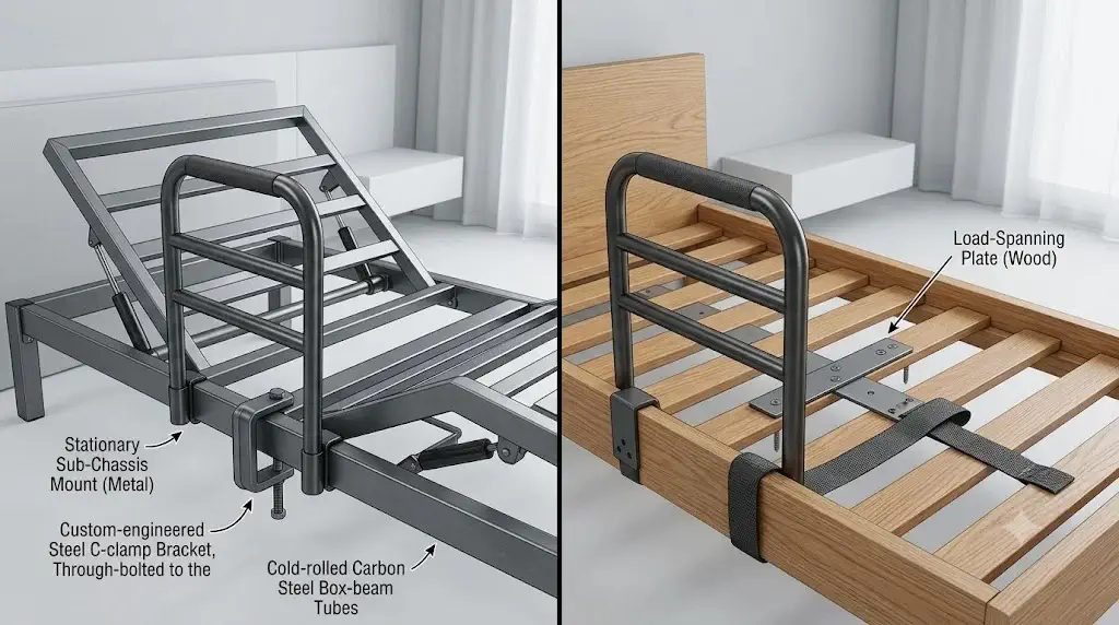
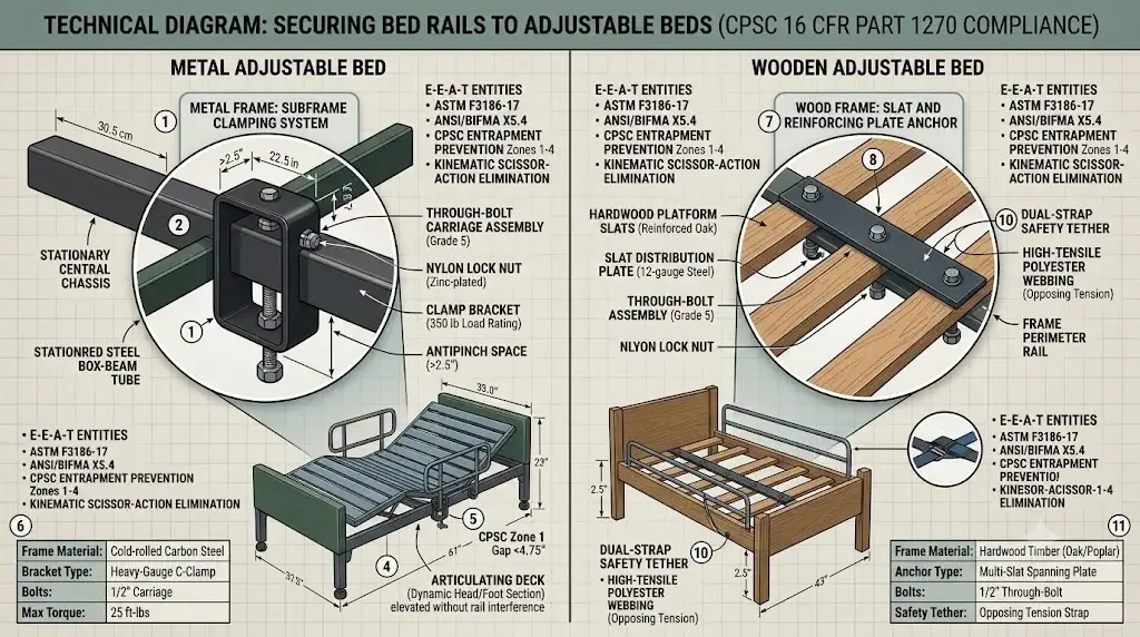
Mastering how to secure bed rails to wooden and metal adjustable beds requires isolating the stationary chassis from dynamic moving components. Installing an assist rail improperly onto an articulating bed presents severe mechanical hazards: clamping hardware to moving head or foot decks induces mechanical binding, strips actuator gears, and generates hazardous gaps that violate CPSC 16 CFR Part 1270 anti-entrapment mandates. A structurally sound installation anchors the rail exclusively to the stationary horizontal center sub-chassis on metal frames using grade-5 clamping brackets, or fastens through-bolted structural plates directly into hardwood foundation slats reinforced by high-tensile polyester safety tether straps anchored to the opposite perimeter rail.
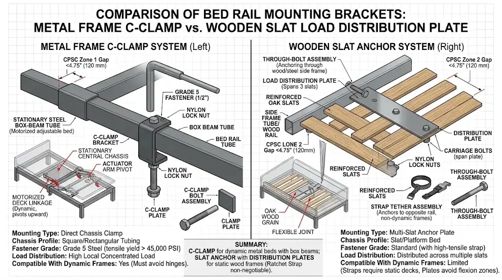
- Metal Frame Fastening: Heavy-gauge steel C-clamps mount directly to the non-articulating rectangular box-beam foundation, leaving articulating pivot points free to move.
- Wooden Slat Anchoring: Reinforcing plates span across at least three continuous hardwood slats, secured with counter-sunk wood screws and opposing tension safety straps.
- Anti-Entrapment Clearance: Assembled safety barriers must maintain under 4.75 inches (120 mm) of gap against the compressed mattress edge throughout the entire 60-degree lift cycle.
Quick Reference Specification: Bed Rail Mounting on Adjustable Frames
The technical specification matrix below compares mounting hardware parameters, load ratings, and compatibility constraints across wooden and metal adjustable bed foundations:
| Installation Parameter | Metal Adjustable Frame | Wooden Slat Platform | CPSC Safety Benchmark |
|---|---|---|---|
| Primary Anchor Location | Stationary central rectangular box beam | Solid timber slats (center third of deck) | Must avoid dynamic scissor hinges |
| Mounting Hardware Type | Heavy-gauge carbon steel C-clamps & U-bolts | Wood screws + through-bolted backing plate | Tensile yield > 45,000 PSI |
| Secondary Safety Tether | High-tensile polyester strap with cam buckle | Opposing frame anchor safety strap | Resists 50-lb lateral displacement |
| Static Shear Load Rating | 350 to 400 lbs (158.7 to 181.4 kg) | 300 to 350 lbs (136.0 to 158.7 kg) | ANSI/BIFMA X5.4 & ASTM F3186 |
| Max Internal Bar Clearance | Strictly under 4.75 inches (< 120 mm) | Strictly under 4.75 inches (< 120 mm) | Zone 1 Entrapment Prevention |
| Articulating Deck Clearance | 2.5 inches clearance from hinge arms | Not applicable (Flat stationary slats) | Pinch-point and shear mitigation |
| Floor Leg Usability | Strictly Prohibited (Stationary legs clash) | Fully Compatible (Static flat deck) | Eliminates structural frame twisting |
Kinematic Mechanics: Isolating Moving Deck Linkages from Stationary Subframes
Motorized adjustable beds generate up to 1,200 Newtons of linear actuator thrust during elevation cycles. When an electric adjustable bed articulates, its tubular head deck pivots upward to a 60-degree angle while the knee hinge arches upward into a 45-degree contour. If a caregiver installs an assist rail across both the moving deck and the stationary base, the linear motor transforms the rigid steel rail into a high-torque mechanical clamp, crushing the bed frame or burning out the motor transformer within seconds.
To execute a mechanically sound installation, engineers must differentiate between the dynamic articulating deck and the stationary sub-chassis:
- The Stationary Central Sub-Chassis: This non-moving steel framework houses the motor brackets and connects directly to the floor legs. Fastening assist handles to this central zone ensures the rail remains stable regardless of how high the user elevates their head or feet.
- Scissor Linkage Pinch Zones: The rotating steel arms connecting the linear actuator to the deck create acute scissor pinch points. Clamping hardware must maintain at least 2.5 inches of clear space away from these moving joints to avoid catching fingers, bed sheets, or electrical cabling.
- The Floor-Leg Incompatibility Rule: Never install bed rails equipped with vertical floor support legs on adjustable beds. When the bed frame tilts, the downward shift bends vertical support legs outward, pulling mounting brackets completely off the frame.
For seniors who sleep on traditional stationary box springs rather than motorized platforms, exploring our definitive testing roundup of sturdy bed assist rails provides heavy-duty ground-supported alternatives.
Metal Subframe Clamping: Heavy-Duty C-Brackets and Grade-5 Fastener Torque
Cold-rolled steel box beams require heavy-duty clamping hardware to resist rotational transfer moments. Standard retail bed rails often ship with lightweight thin-gauge sheet metal brackets that bend when exposed to dynamic adult body weight. When an individual pushes downward and outward to stand up, that pushing force generates over 110 pound-feet of rotational torque along the frame beam.
Structural Metal Clamping Protocol
- Select Direct-Clamping Assist Bars: Choose an assist rail engineered with universal steel clamping brackets designed specifically for rectangular metal bed tubes (typically 1.0 to 1.5 inches square).
- Position Along the Stable Mid-Chassis: Place the clamping brackets onto the stationary center beam of the bed frame, locating the grab handle right at the user’s waistline when seated.
- Tighten High-Tensile Bolts Evenly: Use Grade 5 carbon steel carriage bolts fitted with split lock washers and nylon lock nuts. Tighten each bolt to 25 foot-pounds of torque using a torque wrench. Avoid overtightening, which can crush thin-walled tubular frames.
- Engage High-Tensile Safety Webbing: Wrap the reinforced polyester safety tether strap tightly around the opposite fixed chassis rail. Pull the strap taut through the steel cam buckle to neutralize lateral pulling forces.
Wooden Platform Anchoring: Multi-Slat Load Distribution Plates and Screws
Solid timber slats flex under point loads and require multi-slat distribution plates to prevent wood splitting. Soft pine or flexible birch slats found in standard platform beds bend under concentrated localized forces. If an adult puts 200 lbs of weight on a rail attached to a single wooden slat, the wood can crack along its grain, causing the assist rail to detach suddenly.
Securing a bed assist handle to a wooden slat foundation requires a multi-point anchoring strategy:
- Install a Steel Load-Spanning Plate: Place a rigid 12-gauge powder-coated steel distribution plate across three to four consecutive wood slats. This spans the downward force over a wider surface area of the bed platform.
- Direct Fastening with Wood Screws: Secure the mounting plate through pre-drilled pilot holes into the wood slats using #10 x 1.25-inch stainless steel pan-head wood screws. Never screw into knots or along split grain lines.
- Dual Counter-Tension Tether Straps: Route heavy-duty nylon safety straps completely underneath the slats to the far side of the bed frame. Loop the strap around the solid wood side rail and tighten the ratchet buckle to clamp the rail firmly against the frame.
Entrapment Safety Compliance: Measuring CPSC 16 CFR Part 1270 Clearances
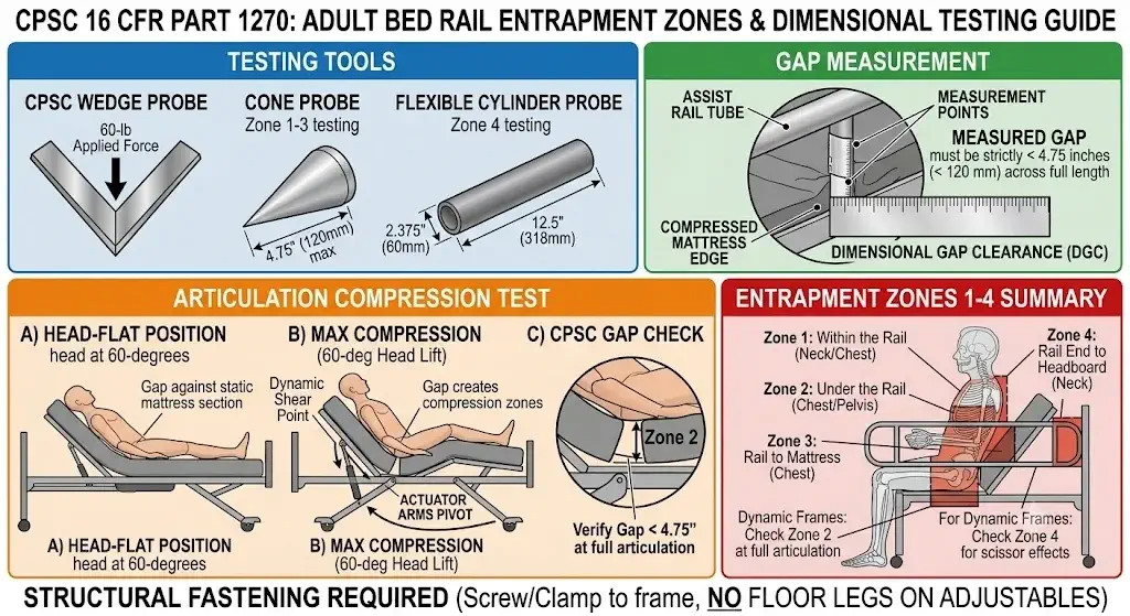
Federal safety standards mandate strict dimensional gap limits to protect vulnerable adults from lethal head and neck entrapment. The U.S. Consumer Product Safety Commission enacted mandatory standard 16 CFR Part 1270 (incorporating ASTM F3186-17) to eliminate dangerous spaces between bed rails and mattresses where seniors could become trapped.
Zone 1 & Zone 2 Gap Dimensions
Openings within the bed rail frame (Zone 1) and between the bottom rail and the top of the mattress (Zone 2) must remain strictly under 4.75 inches (120 mm). This spacing prevents the human head and neck from passing through the framework.
Zone 3 & Zone 4 Perimeter Clearances
The horizontal gap between the rail and the mattress perimeter (Zone 3) must never exceed 4.75 inches when subjected to 50 lbs of pulling force. Zone 4 gaps (between the rail ends and the headboard) must measure either under 2.375 inches or over 12.5 inches to prevent neck trapping.
The Mattress Articulation Compression Test
After installing the bed rail, cycle the adjustable bed to its maximum elevation while checking the gap against the mattress. When the head of the bed elevates, flexible foam and hybrid mattresses compress and pull away from the bed rails. If this movement opens a gap greater than 4.75 inches, reposition the rail closer to the center of the bed or install an approved anti-entrapment gap filler wedge.
Installation Protocol: Step-by-Step Verification and Torque Checklists
Systematic installation protocols eliminate installation errors and ensure safe everyday use. Following a methodical process guarantees that both mechanical fasteners and tension safety straps perform reliably under daily transfer loads:
- Strip the Bedding and Mattress: Remove all sheets, mattress toppers, and the main mattress to expose the bare frame and articulating linkages.
- Locate the User Egress Pivot Point: Have the senior sit comfortably on the bed edge to determine the ideal hand placement point—typically aligned with the pelvis when seated upright.
- Affix Clamping Hardware to the Stationary Beam: Position the mounting brackets on the non-moving steel subframe or across three hardwood slats. Secure the hardware finger-tight first to check positioning.
- Route and Lock the Opposite Anchor Tether: Run the high-tensile safety webbing horizontally across the bed frame. Loop it around the opposing structural beam and secure it tightly with the cam buckle.
- Final Torque and Frame Tightening: Tighten all bolts and mounting screws to recommended torque specifications, confirming the brackets do not slip along the frame beam.
- Full Power Articulation Verification: Reinstall the mattress and cycle the electric bed through its full range of motion. Confirm that the mattress moves smoothly without catching or pulling on the newly mounted bed rail.
Building an Integrated Bedroom Recovery Ecosystem
Securing bed assist handles to wooden and metal adjustable beds creates a stable, fall-resistant transfer point. To maximize independence and support recovery, complete your bedroom setup with complementary mobility hardware:
- Pair your bedside assist handle with adjustable clinical overbed tables to keep meals, medications, and devices easily accessible.
- To review ground-supported assist handles for standard non-adjustable beds, consult our guide to sturdy bed assist rails.
- Maintain continuous support from bedroom to bathroom by reviewing our installation guide for installing shower grab bars.
Frequently Asked Questions (FAQ)
Can you install traditional floor-supported bed rails on motorized adjustable beds?
No. Rigid floor-supported bed rails have fixed vertical legs in continuous contact with the bedroom floor. When a motorized adjustable bed elevates the head or knee deck, the moving mattress frame clashes with the stationary rail, bending the metal tubing, burning out actuator motors, or opening lethal entrapment gaps.
Where should a bed rail be attached on an adjustable metal frame?
A bed rail must always attach to the stationary horizontal sub-chassis—the non-moving central base frame that rests on the floor support posts. Never clamp mounting brackets to the articulating head deck or knee hinge linkages.
How do you prevent bed rails from sliding out of wooden slat beds?
To prevent bed rails from slipping through wooden slats, installers must use dual high-tensile safety anchor straps wrapped around the opposite side rail, combined with direct wood screws securing the rail’s horizontal base plates into solid hardwood cross slats.
What is the maximum allowable gap between a bed rail and mattress under CPSC safety rules?
Under CPSC 16 CFR Part 1270 and ASTM F3186-17 standards, any horizontal gap between the inner rail surface and the side of the mattress must measure strictly less than 4.75 inches under 50 lbs of pull force to prevent head or neck entrapment.
What tools are required to secure a bed rail to a metal platform frame?
Mounting a bed rail to a metal box frame requires an adjustable open-end wrench set, hex keys, heavy-duty C-clamp brackets, and a torque wrench to tighten Grade 5 carriage bolts to 25 foot-pounds without crushing hollow steel tubing.
